ISTE Standards & NGSS Science & Engineering Practies

Sunday, December 20, 2015

Blinking Alien Spaceship Book Using Neopixels & an ATtiny85


Solder the neopixels before removing the adhesive from the copper tape.
In the process of prototyping, to see if I could get individually addressable neopixels (surface mounted RGB LEDs) to work in a paper circuit, I've learned a couple of tricks.
The most important one is to solder the LEDs to the copper tape before creating the rest of the circuit. Compared to my first botched attempt, in which I tried to solder neopixels to copper that was already adhered to paper, soldering the LEDs to the copper first was far less fiddly.
Although I had to use a multimeter to isolate a wonky joint (the result to too many cross-overs) I was eventually able to get three LEDs to work the way I'd intended.  Each light changes colors!

In this project, I've added a LilyPad button board in addition to a LilyPad slide switch.


Something else that I've done differently is add two layers of watercolor paper to the binder's board, with notches cut out for the LEDs, button, and switch.  Neopixels are thicker than other SMD LEDs, so the extra paper helps smooth out the surface of the book covers.  I added one layer of watercolor paper to the inside covers as well, hoping to increase the surface tension on the battery. 

Rough sketch
I painted the design and sealed it with acrylic gel medium.


Saturday, December 19, 2015

Alien Paper Circuit with Neopixels & an ATtiny85

Chainable, surface mounted RGB LEDs work in paper circuits! 

After spending a couple of days prototyping, I've completed my first paper circuit using individually addressable neopixels, otherwise known as surface mounted RGB LEDs! Soldering them was trickier than I'd anticipated, however!  I'd originally planned to use three lights in this model, but a soldering mishap resulted in my using only two.  I love the way that the lights change colors at the press of a button!  (See video below).


Thursday, December 3, 2015

Video: Programming an ATtiny85 Microprocessor with a Chromebook

Updated 30 October 2016:  Codebender is closing.  

Programming an ATtiny85 with a Chromebook

I recently completed a video tutorial to teach others how I program the ATtiny85 using a Chromebook.
I'm cross-posting it to this blog as a resource for budding notebook hackers.


Tuesday, November 10, 2015

ATtiny85 Resources

TinyAVR Programmer and Arduino Uno with ATtiny85
I originally started writing about my experiences programming the ATtiny85 on another blog, but it has been brought to my attention that some of you may have been looking for that documentation here.

As a result, I'm cross-posting to help those interested find the information they are seeking, particularly those of you I may have chatted with during Lucie's Making with Code:  Let's Get Physical workshop at Vermont Fest on 6 November.

I've also been asked where to purchase the chips, as well as the method that I prefer when programming the ATtiny85. While I use a TinyAVR programmer for programming circuit sticker microprocessors, I prefer using an Arduino Uno with my ATtiny85's for the following reasons.

1)  It's easier to remove the chip without accidentally bending the legs.

2)  You can set up a breadboard with LEDs to immediately test the code on your ATtiny85.

3)  A lot of people have Arduino boards kicking around (but don't know what to use them for).

Some time early next year I hope to teach another workshop or two geared towards educators and students, as a large number of you expressed disappointment that you were unable to attend the Notebook Hacking session at Vermont Fest.

Tuesday, November 3, 2015

How to Solder Surface Mounted LEDs in Paper Circuits

Soldering has brought me so much unexpected happiness, that it's hard for me to believe that I didn't learn how to do it until two summers ago. Better late than never! Thank you, +Craig Lyndes, for teaching me how to solder!

Since a lot of people have asked me how I solder surface mounted LEDs in my projects, I decided to create this video for a class I'm taking.

If you haven't yet tried your hand at soldering, I hope this will motivate you to grab a soldering iron, crack a window and a smile, and have fun!  (You may need to change the video settings to HD 720 once it starts.)


Thursday, October 22, 2015

Notebook Hacking Podcast

I created this podcast for a class that I'm taking but decided to share it here for those interested in learning more about Notebook Hacking.


AG Planning a Notebook Hacking Activity for 7th Graders

Monday, September 14, 2015

Maple Leaf Book

Maple Leaf Book

Brainstorming


Paper Circuit Embedded into Book Cover
After experimenting with some Arduino sample code, I ended up creating a circuit that resembles a leaf when it's in action.

I'd originally set out to create something a bit more abstract, but a maple leaf emerged from the mess of solder and copper tape.


For the cover boards, I painted 2-ply Bristol with Jacquard Lumiere paints.


Keith A. Smith's "Broken H's" binding

Magnetic Flap to Hide Battery

Tuesday, August 25, 2015

Blinking Halloween Tunnel Book


Observing from the sidelines, the ritual of my teacher friends attending in-service and frantically preparing their classrooms, is bittersweet.  Gratefully, as summer winds down and a new school year starts, the promise of autumn's delights remains for me a pleasant distraction.   Although I miss having a classroom of my own, I appreciate the creative incubation time that freelance work allows.


In preparation for a paper circuitry workshop that I'm teaching in October, I decided to construct a blinking Halloween tunnel book as my latest project.  Like the Roadrunner tunnel book that I made earlier this summer, this one is illuminated by a paper circuit controlled by an ATtiny85.

I got started by drawing some spooky shapes on white card stock and cutting them out with a pen knife.  When I was happy with the templates, I traced the designs onto black card stock.

I backed the last layer with a piece of copy paper to diffuse the light.

Here's an illuminated view.
A view of the book taken in daylight.

I opted to use a paper battery holder, rather than alligator clips.
My circuit is quite a mess, because I didn't plan it well at the start.

Tuesday, August 18, 2015

Paper Circuit Mini-Book with New Materials from AgIC


For this little book, measuring approximately 3 1/2" tall by 4" wide, I stepped away from copper tape, my soldering iron, and microprocessors to try out AgIC's erasable Circuit Marker (and some other goodies that they sent my way).

The first thing that I'd like for you to notice about the video embedded below is how the tiny LEDs are flashing in a somewhat random pattern. Would you believe that these little surface mounted LEDs are blinking on their own, rather than being controlled with a micro-controller or effects sticker?

While it's not difficult to find standard 5mm LEDs that twinkle, this is the first time that I've encountered surface mounted LEDs that flicker!  AgIC sent me five of them (and I am in love).  I've since discovered that you can order them on eBay.


I created this little book using materials in the AgIC Circuit Marker Starter Kit, two magical surface mounted LEDs, and basic craft materials.

Tools
AgIC Circuit Marker, Circuit Eraser, and Circuit Stencil
Bone folder
Ruler
Piercing tool
Needle
Cutting Mat
Pen Knife
Colored Pencils
Paper Clip

Materials:
1 sheet AgIC Circuit Paper (or a sheet of photo paper cut 3 1/2" X 5 1/2")
4 sheets of text-weight paper cut 3 1/2" X 8" and folded in half
2 sheets of colored cover stock cut 3 1/2" X 8 1/4" and folded in half
1 sheet of white cover stock cut 5" X 9" and folded in half
5 inches of linen thread or embroidery floss
1 coin cell battery with tabs
3-4 inches of aluminum tape
2 SMD LEDs (unless you have the special ones from AgIC, yours will probably not twinkle on their own)
Scotch tape

Directions: 
1. Lay a sheet of AgIC Circuit Paper down lengthwise, shiny side down. Measure and score it 4 inches from the left edge and fold it so that the shiny surface is on the outside. Position the paper so that the crease is on your left and the largest part of the paper is on the top.

2. To create a signature, or booklet, nest the folded text-weight paper inside of the folded cover stock. Wrap the Circuit Paper around the outside, the large, shiny surface on top; this will be where you'll be drawing your circuit.

3. Clip the layers together to keep them from slipping and use the piercing tool or needle to poke three holes through them, one in the center and the other two at equal distances from the top and bottom.

4. Use a pamphlet stitch, starting from the outer center hole, to secure the booklet. Tie it off and trim the ends to about an inch.  These will be hidden inside of the finished book.


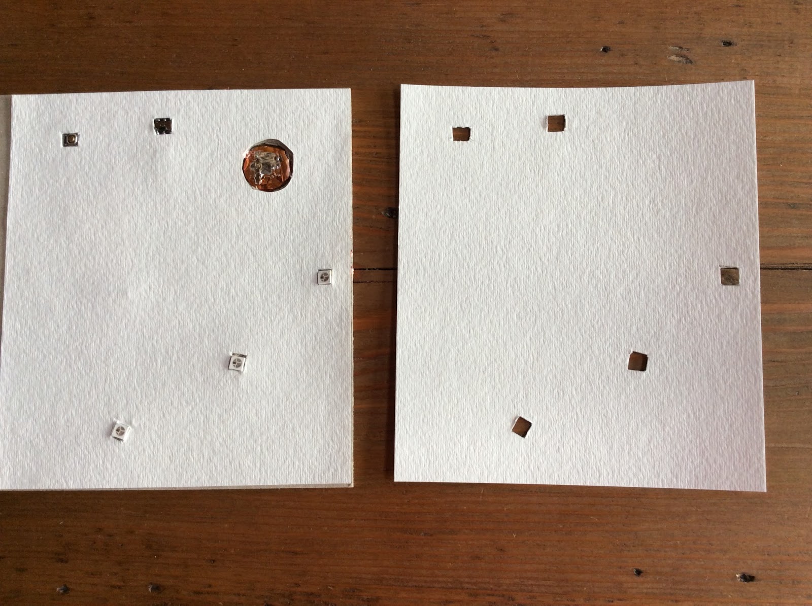
5.  Use the stencil to draw contacts for your battery.  Design your circuit the way you want it.  I wanted to create a push switch, so I also drew contacts for a switch at the top.


6.  Place your battery on top of the circuit and tape down the terminals with small pieces of aluminum tape. Position the SMD LEDs where you want them, ensuring that the polarity of the LEDs matches the circuit, and tape them down securely.


7.  Test your switch by holding a piece of aluminum tape over the switch terminals.  If all looks good, it's time to design your cover.


8.  To make the slip cover, lay the 5" X 9" of white cover stock on a table and center the open book block on top of it.


9.  Use a ruler or another straight edge to score a line across the top of the book block.  Repeat this step for the top and bottom edges.


10.  Fold along the scored edges.


11.  Place the book block back into the center and fold up the left and right sides of the cover to fit it.  This doesn't have to be perfect.  The idea is that the removable cover will fit snugly when the first two pages of the booklet are inserted in the slots that are formed from folding.


12.  Place a piece of aluminum tape on the inside of the removable cover so that it will make contact with the switch terminals that you drew earlier.


13.  Assemble the book. Make sure that the circuit works when you press down on the area of the front cover that has the foil backing.


14.  Verify the location of your LEDs.  Take off the cover to complete your artwork!


15.  Voila!  To light up the LEDs, press the switch; use a paper clip to close the switch and maintain the connection.  To conserve battery life, remove the paper clip to open the switch!


Reflections:
I had to make quite a few different prototypes before I arrived at one that I was happy with.  While I have experience working with circuits and a variety of conductive materials, using new materials required me to work differently and think differently about my process.

Before settling on this design, I attempted to embed the tabbed battery into a piece of binder's board by cutting a recess in the material, with the idea of gluing my design over the circuit.  This approach was problematic because the special circuit paper has a glossy surface that doesn't play well with wet glue. Double-stick tape would have worked, but I was also concerned that the tape might lose some of it's stickiness over time.

While the conductive ink works like a charm, and erases easily (which is a huge bonus), my biggest difficulties occurred when re-positioning the LEDs.  Each time I did so, even if it was just slightly, I had to remove the tape.  Moving the tape left a residual adhesive on the special paper that ended up interfering with the connection of my circuit!  Since I only had three pieces of the special paper to play with, each a little bigger than a small index card, I resorted to using photo paper for the finished project.

Once I decided upon glue-free book model, my process went very smoothly!  A Circuit Marker is a perfect tool for making greeting cards or artwork where the circuit is central to the aesthetic of the design.  So, while I don't think that I'd use a Circuit Marker for bookbinding that might be wet and gluey, I love the idea of having another creative tool that is portable and doesn't require solder.


Thursday, August 13, 2015

Puttering with Light Sensors

Thanks to the work of David Peins, I am continuing to learn about surface mounted sensors.

I've observed that this circuit (which contains an SMD phototransistor) is different from the one that I created with a photo-resistor.

1.  The LED in this circuit turns off in bright light, while the LED in my other circuit was programmed to turn on when it's dark.

2.  The SMD components in this circuit are more elegant, but are trickier to work with.

Next Steps:
Try to get this circuit to work with an Attiny85.

Figure out a practical way to use this in a project


Wednesday, August 12, 2015

Sugar Skull Book is Complete


I embedded a switch, Attiny85, and a 3V coin cell battery.
This is the front view of the front cover.


After doing quite a few sugar skull prototypes, I have finally used the design in a book binding project!  I plan to fill this 8 X 8 inch journal with pictures of my parents and momentos from Arizona.

Something that worked well here was using a copper-colored acrylic ink to paint around the artwork, rather than leaving the Canson mixed media paper a boring white. Sealing the colored pencil sketch with acrylic gel medium gives the cover an additional glow.


While I am generally happy with the way that this book turned out, I've concluded that I may need to use a thicker binder's board if my goal is to do an elegant job of hiding a recessed battery.

In this model, the majority of my focus was on getting the artwork to line up with the circuit. If I could go back and do it all over, I would position the hole for the battery another half inch away from the corner to provide more wiggle room for creating a flap to conceal it.


I had fun soldering the LEDs to the copper tape, but one of the LEDs that I selected for the eyes stopped working after I sewed the signatures into the book!

After bending the cover a bit, it worked again, but now my front cover has a slight bend to it.
I wish the hole for the battery was further from the corner!
   
This is the back view of the front cover.
Here's how I laid out my circuit.


The inside features a variety of different papers; I plan to decorate them later.