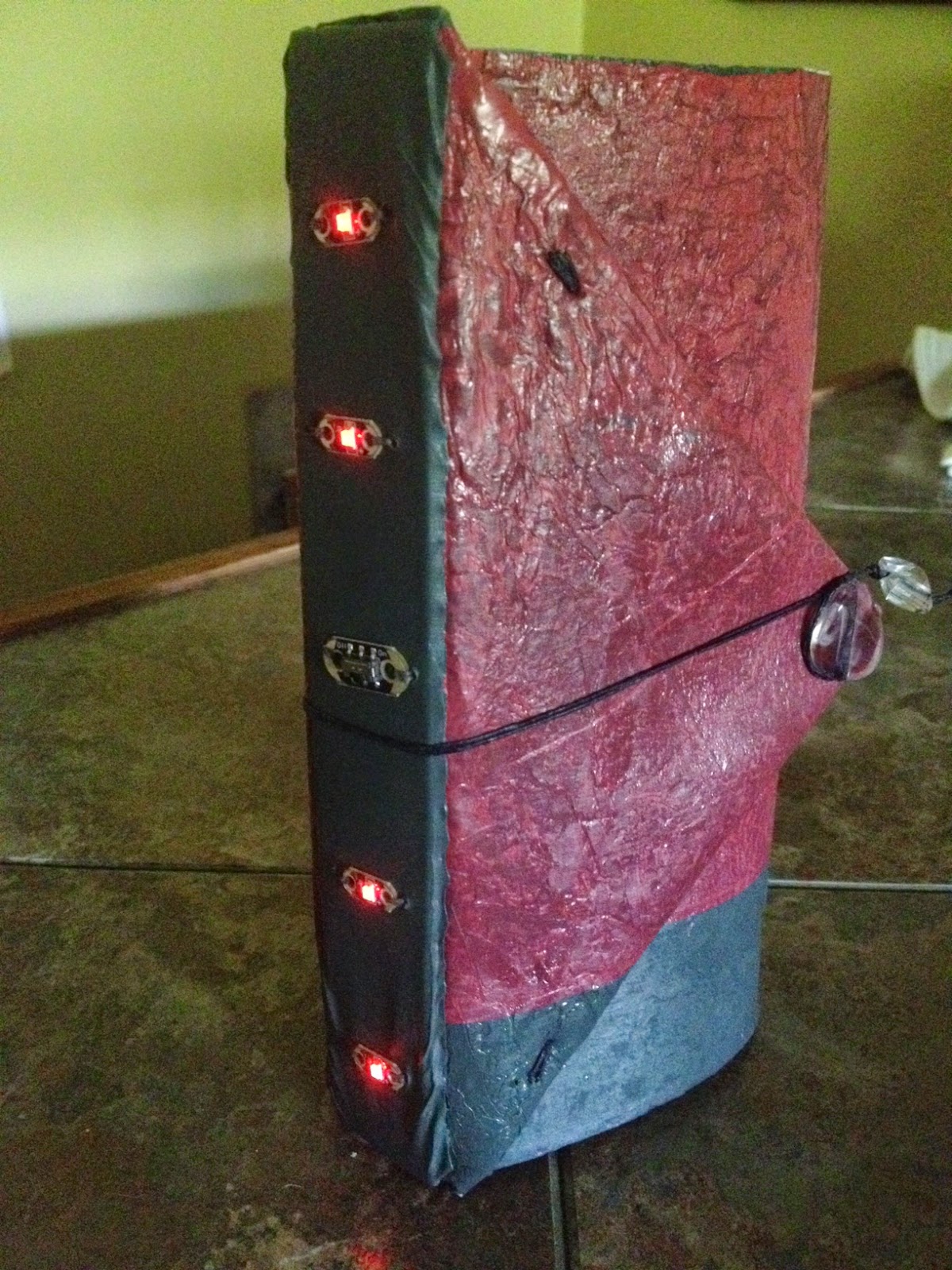
ISTE Standards & NGSS Science & Engineering Practies

Monday, October 6, 2014

Spooky Circuit Box

Spooky Circuit Box

I created this box as a prototype for an activity that I am planning on leading for young people during the Vermont Tech Jam later this October.  After scouring the Internet, I found a useful Slide Share tutorial about building a circuit box that I have adapted and illustrated here.


Below, I have added precise dimensions that work well for constructing a box, as well as a couple of aesthetic improvements that also improve the overall functionality of the original design.

You will need the following tools and materials:

Useful Tools & Supplies:
bone folder
piercing tool
1 LED light
11-12 inches of adhesive copper tape
painter's tape
1 3V coin cell battery
rubber stamps and ink or other art supplies
card stock
ruler
scissors
pen or pencil


Directions: 

Box Top
1.  Prepare a 5 7/16" X 5 7/16" piece of orange card stock by decorating it with a rubber stamp or original artwork.  (Rounding up to 5 1/2" made the box a bit looser than I liked).  Keep in mind that the LED will be going through the center of the paper after it's folded.  (If you want a bigger box, use an 8 1/2" X 8 1/2" piece of paper)

2.  Fold the paper in half diagonally.  When folding, match the corners and edges carefully, creasing the edge with the bone folder.  Open.  Repeat for the other diagonal.


3.  Fold each corner to the midpoint of the square. Crease. Open to observe four new points of intersection.

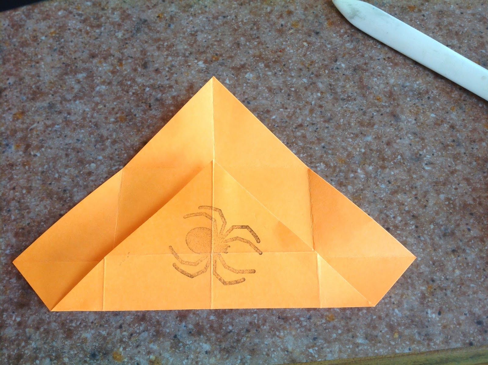
4.  Fold each corner to the newest points of intersection. Crease. Open.


5.  Turn the paper over and fold each of the four corners to the nearest point of intersection. Crease.  Open.


5.  Turn the paper over again and fold it in half across the center to form two rectangular halves.  Crease.  Repeat in the other direction.


***(SKIP THIS STEP WHEN YOU ARE MAKING THE BOX BOTTOM)***
6.  Unfold the paper to expose the unadorned side.  Use a pencil and a ruler to draw a line parallel to each edge of the box that divides the 3 outermost squares along each edge in half along the diagonals of the squares.  Cut along these lines.


7.  Fold each new corner to the midpoint of the square and open, making 4 new fold lines. Unfold.

8.  Fold two opposite corners to the midpoint.

9.  Position the walls upright.  The walls of the lid will be half the depth of those of the bottom lid.

10. Fold in the remaining two corners, pushing in the diagonal folds at each corner as you position the wall and the triangles at the bottom of the box.

Box Bottom
1.  To make the bottom of the box, fold a piece of 5" X 5" card stock and follow the steps for making a Box Top.  (or if making a bigger box, use an 8 1/4" X 8 1/4" of paper).  Be sure to skip Step 6!

Adding the LED


1.  Use a piercing tool to punch a hole through the center of the lid.

2. Insert the legs of the LED through the top side of the box top.


                                                                                                                     ***IMPORTANT***
Do your best to keep the copper tape straight and centered on the box (so that it matches up with the box bottom).
3. Turn the lid upside down. Before opening the legs of the LED, apply a 2 3/4" strip of copper tape (longer if making the bigger box) to the box top under each leg of the LED. Some of the copper tape will wrap around to the outside of the lid. Spread the legs of the LEDs.


4.  Tape the LEDs down and denote which end is the positive side and which is the negative side.


5.  If you wish to cover up the tape, insert a piece of 1 15/16" X 1 15/16" orange card stock into the lid.  Mark the positive and negative sides on the insert.

If making the larger box, the insert will need to be  (2 15/16" X 2 15/16")


Completing the Circuit
1.  Lay a 2 3/4" strip of copper tape down that starts at the center of the box bottom and wraps around to the outside edge of the box.  This will be the negative lead.  (Your tape will need to be longer if you are making the bigger box.)

                         ***IMPORTANT***
Do your best to keep the copper tape straight and centered on the box (so that it matches up with the box top).


2.  To create the positive lead, place your battery negative side down on top of the negative lead and then lay a 2 3/4" strip of copper tape over the positive side of battery.  At the end of the tape that will be in contact with the positive side of the battery, fold 2-4 mm of the copper tape onto itself to make it more conductive.  Press the copper tape down firmly and continue around the top edge of the box.   
3.  With your battery negative side down, under the positive lead, fasten it with tape.  Mark the positive and negative leads.


Test the Circuit
1.  Put the box together, being careful to match the positive leg of the LED with the positive lead connected to the battery.  You will need to gently squeeze the sides of your box in order to ignite the circuit.  If it doesn't work, check to ensure that your polarity is correct.


Box Divider
If the circuit is working properly, and you want to cover up the battery, use the 3 1/4" X 3 1/4" piece of orange card stock to create a divider.


Thursday, September 4, 2014

Zentangle Journals


These are my latest creations.  While I have not demonstrated any new breakthroughs with my understanding of electronics with these particular models, I did make several improvements over the original versions.

Like the previous models, I used conductive thread to sew the LEDs to the spine, and I connected the threads to a battery held in a paper holder.


Unlike the previous models, I did not connect my signatures to the conductive loops of thread that were formed when attaching the LEDs.

Instead, I added a strip of Tyvek over the conductive loops on the inside of the spine and then re-entered the holes attaching the LEDs using a thin linen thread.  I then sewed the signatures to the linen thread loops.  Over time, I suspect that this will result in a more durable book.

Something else that I did differently was decorate my covers with Zentangle illustrations and acrylic inks.  I also improved the structure by sewing a third signature into each model.


Saturday, August 23, 2014

Light-up Wrap Book with a Switch and a Recycled Plastic Bag Cover

I created this model as an experiment to see if I could create a book cover from recycled plastic bags and cardboard.  I wanted to see whether a cover made from recycled materials might be a practical alternative to watercolor paper, for use in a classroom setting.

Ultimately, I was looking for an affordable way for teachers to construct something similar to this with their students.

I've determined that while I personally prefer the look, feel (and smell) of paper covers, using plastic bags  is a viable option.  The covers are durable, and students could easily use an awl (rather than a drill) to poke holes in the spine to sew on their LEDs.

The biggest concern that I have for using this particular structure as an artists' journal would be that the spine can only accommodate the addition of two signatures.  With my current design, the signatures are being sewn onto the loops of conductive thread that are created on the inside cover when the LEDs were sewn to the outside of the covers.  Over time, I worry that the conductive thread will start to fray, leading to malfunctions in the LEDs.  This structure would be much more durable if there were some other loops to hook the signatures on to.

If I do this again, I will change the dimensions of the overall book to be a 4" X 4" square.  I will also add ornamental loops to the spine that will serve as supports for extra signatures and use a lighter-weight paper for the signatures.  I might also try to sew designs or a pocket flap onto the plastic using a sewing machine, before binding the book.

Here is a basic explanation of how I created this plastic book cover.


Monday, August 18, 2014

Standards and Rubric

Check-In

This blog documents the work that I have done to combine electronics with bookbinding.  Here are some of the items that I have been working on.  I still have ideas that remain works in progress. Throughout the process, I've added posts about each creation.  I plan to continue adding to this blog as I create and learn more.

(I used the following apps to create this video:
iStopMotion, DoInk, GreenScreen,
Tiltshift, iMovie, and Magisto.)

Assessment:

I adapted the Buck Institute's Creativity and Innovation Rubric for my assessment.  You may link to my adapted rubric by clicking on the tab labeled Rubric at the top of this page.

ISTE Standards & NGSS Science & Engineering Practices:

To view the standards most closely associated with my project, click on the tab labeled Standards at the top of this page.


Sunday, August 17, 2014

Revised Model


In an earlier post, My First Blinged-Out Book, I was thrilled that I had a solid working model, even though I suspected that I might have a power supply problem that needed fixing.  
Today, I revised the cover to add a switch and a LilyPad Tiny Twinkler.  I am most proud of the fact that I was able to get five LEDs to twinkle this time!


(See it in action in the video below).

I lined the front cover with a couple of layers of felt to accommodate the bulk of the battery.


NGSS Framework Practices Addressed

1.  Asking questions (for science) and defining problems (for engineering)
2.  Developing and using models
3.  Planning and carrying out investigations
4.  Analyzing and interpreting data
5.  Using mathematics and computational thinking
6.  Constructing explanations (for science) and designing solutions (for engineering)
8.  Obtaining, evaluating, and communicating information