ISTE Standards & NGSS Science & Engineering Practies

Showing posts with label ATtiny85. Show all posts

Tuesday, October 16, 2018

Light-up Monsters: Altered Books


In the spirit of Halloween, I've created a couple of altered books with circuits built into the covers.  Glow-in-the-dark polymer clay makes up the eyes, tongues, and teeth.  To create the light-up effect, I drilled holes through the eyes, inserted LED bulbs into them from underneath, and then poked the legs through the front covers.  I used hot glue to secure the eyes to the tops of the books and to fill in the drill holes.  


My first monster model uses a 5V Trinket with a Micro-Lipo Charger soldered to it.  The two LEDs are then soldered in parallel to analog pin one.  I used Arduino sample code to achieve a creepy fading effect.  After completing this circuit, I decided that the use of the charger was overkill, adding more bulk than I wanted.


The second model substitutes a Trinket with 3V logic and a switched JST breakout board.  This method is less expensive and more compact.


Thursday, April 14, 2016

Using a TinyAVR Programmer with Codebender

Updated 30 October 2016:  Codebender is closing.

Here's a tutorial I put together to help you get started.  Under Codebender's Terms and Conditions, students must be 13 or older to use Codebender.

The TinyAVR Programmer is available at Spark Fun.


Sunday, February 7, 2016

Flying Saucer: I've got a servo running on an ATtiny85, thanks to Jeannine Huffman!


I have been following Jeannine Huffman's (and Jim Bock's) work of getting a servo to run on an ATtiny85. When she shared her process, I ordered the parts and got right to work!  I used a TowerPro SG90 hobby motor that I ordered off of Amazon.

My servo moves smoothly for about 30 seconds, but then it sort of stalls out.  It will start again if I turn it off and on again.  I may have issue with my power supply.  I am using 2 coin cell batteries.


This pop-up was a rapid prototype.


Sunday, December 20, 2015

Blinking Alien Spaceship Book Using Neopixels & an ATtiny85


Solder the neopixels before removing the adhesive from the copper tape.
In the process of prototyping, to see if I could get individually addressable neopixels (surface mounted RGB LEDs) to work in a paper circuit, I've learned a couple of tricks.
The most important one is to solder the LEDs to the copper tape before creating the rest of the circuit. Compared to my first botched attempt, in which I tried to solder neopixels to copper that was already adhered to paper, soldering the LEDs to the copper first was far less fiddly.
Although I had to use a multimeter to isolate a wonky joint (the result to too many cross-overs) I was eventually able to get three LEDs to work the way I'd intended.  Each light changes colors!

In this project, I've added a LilyPad button board in addition to a LilyPad slide switch.


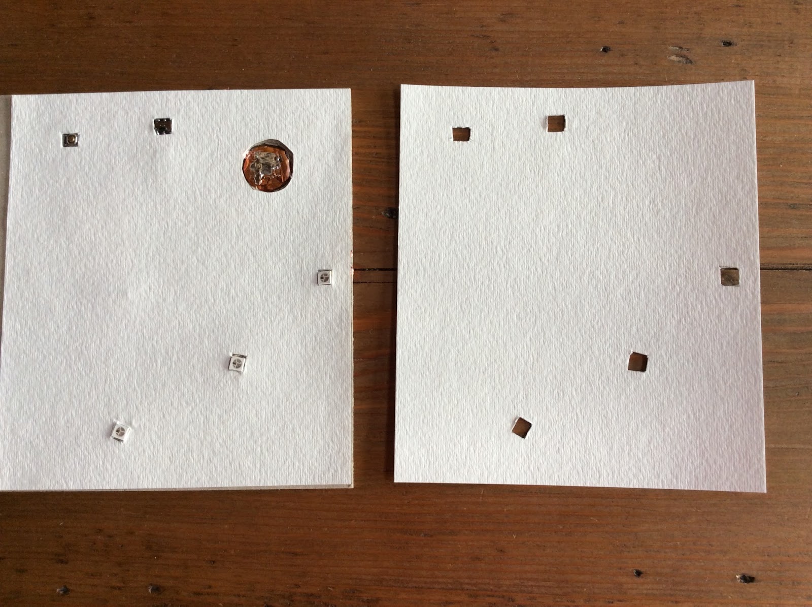
Something else that I've done differently is add two layers of watercolor paper to the binder's board, with notches cut out for the LEDs, button, and switch.  Neopixels are thicker than other SMD LEDs, so the extra paper helps smooth out the surface of the book covers.  I added one layer of watercolor paper to the inside covers as well, hoping to increase the surface tension on the battery. 

Rough sketch
I painted the design and sealed it with acrylic gel medium.


Thursday, December 3, 2015

Video: Programming an ATtiny85 Microprocessor with a Chromebook

Updated 30 October 2016:  Codebender is closing.  

Programming an ATtiny85 with a Chromebook

I recently completed a video tutorial to teach others how I program the ATtiny85 using a Chromebook.
I'm cross-posting it to this blog as a resource for budding notebook hackers.


Tuesday, November 10, 2015

ATtiny85 Resources

TinyAVR Programmer and Arduino Uno with ATtiny85
I originally started writing about my experiences programming the ATtiny85 on another blog, but it has been brought to my attention that some of you may have been looking for that documentation here.

As a result, I'm cross-posting to help those interested find the information they are seeking, particularly those of you I may have chatted with during Lucie's Making with Code:  Let's Get Physical workshop at Vermont Fest on 6 November.

I've also been asked where to purchase the chips, as well as the method that I prefer when programming the ATtiny85. While I use a TinyAVR programmer for programming circuit sticker microprocessors, I prefer using an Arduino Uno with my ATtiny85's for the following reasons.

1)  It's easier to remove the chip without accidentally bending the legs.

2)  You can set up a breadboard with LEDs to immediately test the code on your ATtiny85.

3)  A lot of people have Arduino boards kicking around (but don't know what to use them for).

Some time early next year I hope to teach another workshop or two geared towards educators and students, as a large number of you expressed disappointment that you were unable to attend the Notebook Hacking session at Vermont Fest.

Tuesday, November 3, 2015

How to Solder Surface Mounted LEDs in Paper Circuits

Soldering has brought me so much unexpected happiness, that it's hard for me to believe that I didn't learn how to do it until two summers ago. Better late than never! Thank you, +Craig Lyndes, for teaching me how to solder!

Since a lot of people have asked me how I solder surface mounted LEDs in my projects, I decided to create this video for a class I'm taking.

If you haven't yet tried your hand at soldering, I hope this will motivate you to grab a soldering iron, crack a window and a smile, and have fun!  (You may need to change the video settings to HD 720 once it starts.)


Monday, September 14, 2015

Maple Leaf Book

Maple Leaf Book

Brainstorming


Paper Circuit Embedded into Book Cover
After experimenting with some Arduino sample code, I ended up creating a circuit that resembles a leaf when it's in action.

I'd originally set out to create something a bit more abstract, but a maple leaf emerged from the mess of solder and copper tape.


For the cover boards, I painted 2-ply Bristol with Jacquard Lumiere paints.


Keith A. Smith's "Broken H's" binding

Magnetic Flap to Hide Battery

Tuesday, August 25, 2015

Blinking Halloween Tunnel Book


Observing from the sidelines, the ritual of my teacher friends attending in-service and frantically preparing their classrooms, is bittersweet.  Gratefully, as summer winds down and a new school year starts, the promise of autumn's delights remains for me a pleasant distraction.   Although I miss having a classroom of my own, I appreciate the creative incubation time that freelance work allows.


In preparation for a paper circuitry workshop that I'm teaching in October, I decided to construct a blinking Halloween tunnel book as my latest project.  Like the Roadrunner tunnel book that I made earlier this summer, this one is illuminated by a paper circuit controlled by an ATtiny85.

I got started by drawing some spooky shapes on white card stock and cutting them out with a pen knife.  When I was happy with the templates, I traced the designs onto black card stock.

I backed the last layer with a piece of copy paper to diffuse the light.

Here's an illuminated view.
A view of the book taken in daylight.

I opted to use a paper battery holder, rather than alligator clips.
My circuit is quite a mess, because I didn't plan it well at the start.

Wednesday, August 12, 2015

Sugar Skull Book is Complete


I embedded a switch, Attiny85, and a 3V coin cell battery.
This is the front view of the front cover.


After doing quite a few sugar skull prototypes, I have finally used the design in a book binding project!  I plan to fill this 8 X 8 inch journal with pictures of my parents and momentos from Arizona.

Something that worked well here was using a copper-colored acrylic ink to paint around the artwork, rather than leaving the Canson mixed media paper a boring white. Sealing the colored pencil sketch with acrylic gel medium gives the cover an additional glow.


While I am generally happy with the way that this book turned out, I've concluded that I may need to use a thicker binder's board if my goal is to do an elegant job of hiding a recessed battery.

In this model, the majority of my focus was on getting the artwork to line up with the circuit. If I could go back and do it all over, I would position the hole for the battery another half inch away from the corner to provide more wiggle room for creating a flap to conceal it.


I had fun soldering the LEDs to the copper tape, but one of the LEDs that I selected for the eyes stopped working after I sewed the signatures into the book!

After bending the cover a bit, it worked again, but now my front cover has a slight bend to it.
I wish the hole for the battery was further from the corner!
   
This is the back view of the front cover.
Here's how I laid out my circuit.


The inside features a variety of different papers; I plan to decorate them later.


Wednesday, July 29, 2015

Peach and Purple Book with Embedded Paper Circuitry in Cover


The video above features my latest blinged-out book, a Coptic-bound journal with embedded paper circuitry components and hand-painted watercolor covers.

This is my second attempt to hide and embed the components inside of a book cover.  This iteration worked better than my first (the sparkling Sea Turtle), because I figured out that I could put the finished covers into a book press to keep them from warping if I placed a folded dishtowel between the covers and pressing boards.

Here are the guts of the front cover.  I cut holes for the microprocessor, switch, and battery.


Like the Sea Turtle book, I embedded a switch into the front cover.  While it doesn't look too intrusive, I'd like to figure out a more elegant way to do this.  I'd also like to design a book and a cover that actually tell some sort of story.


The last time I attempted a binding like this (with an embedded circuit), I discovered that there wasn't enough tension on the inside cover flap to keep the copper leads in contact with the battery.  I got around that this time by using an adhesive-backed magnet.  I think that a super thin piece of strong velcro would work equally well. You may notice that I also soldered copper disks to the positive and negative leads to ensure a better electrical connection.


Tuesday, July 28, 2015

My Attiny85 Light Sensor Works!

Forgive my exuberance, but I finally got a photo-resistor to work with my Attiny85, creating the light sensor that I've been trying to figure out for days!

I now have my first programmed paper circuit that is activated by light.

Once I had the resistors in place (something that I'd failed to do the first time I attempted this), my biggest obstacle was figuring out how to code it properly.  Surprisingly, the code was almost identical to that of the sound sensor: only the value read by the sensor was different.

Now that I have a better understanding of how this works, I am really excited to integrate this into a project!

Here's what the circuit looks like.
Here is the code.

The LED blinks when I cover the photo resistor.


Sound Sensor Triggered Paper Circuit


Sugar skulls and sensors have captivated my interest lately.  The video above features my latest paper circuit (another prototype for a potential book cover), powered by triggering a Chibitronics sound sticker sensor. Originally, I'd set out to see if I could use a surface mounted light sensor to trigger the lights on my circuit, but I haven't been able to figure out how to do it without the use of a serial monitor.  Perhaps, I'm making it more difficult than it needs to be; but, I keep hitting roadblock after roadblock.  I can get a photo-resister to work on a regular Arduino board, but I haven't been able to replicate it on an Attiny85.

Update:  I got a light sensor to work!

In any case, getting the sound sensor to work was a breakthrough in and of itself!

Although I am happy with the outcome, I must admit that it took me a couple of days of exploration and failure to get the code to actually work!  My first attempt was a disaster, resulting in my having to cut the Attiny85 off the paper after I'd soldered it down.


Lessons Learned:
1.  I really need to start using my multimeter.
2.  Don't solder your microprocessor until you've verified that the code works.
3.  Not all surface mounted LEDs are created equally.  The super bright ones available from SparkFun are my personal favorite.
4.  Naming the analog pins works differently when using a sensor.  For example, what I'd normally refer to as "Pin 4" is called "A2" in the code (something that I'd like to better understand).